 Congratulations On Your Successful Submission
 Submission Failure
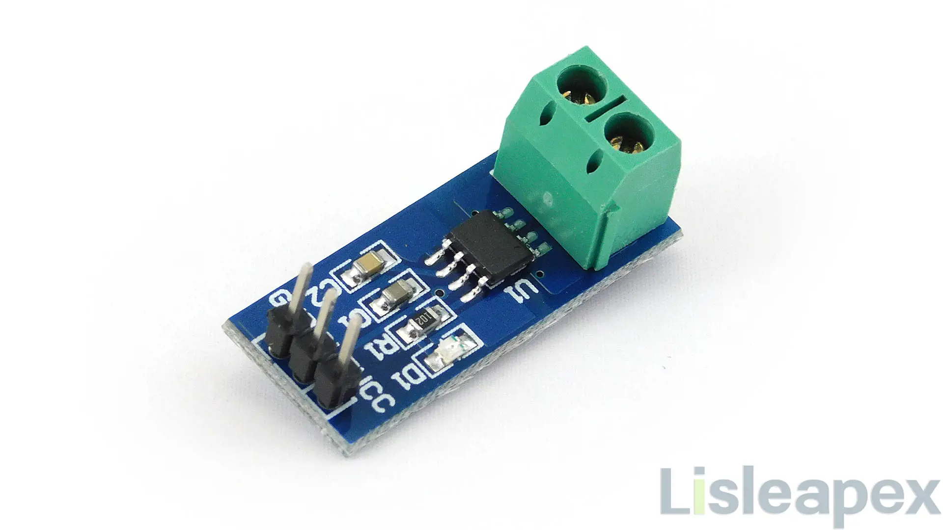
Overview of ACS712 Current Sensor
The ACS712 emerges as an economical and highly precise answer to the complex requirements of AC or DC current sensing. Tailored for applications across diverse sectors, including industrial, commercial, and communications systems, its adaptability is a key asset. Its utility spans various tasks such as motor control, load detection, switch-mode power supply management, and robust overcurrent protection. This versatile sensor delivers reliability and accuracy, catering to an array of needs within electronic systems across industries.
Where to Use ACS712 current sensor
The ACS712 current sensor, leveraging the renowned ACS712 IC, operates on the Hall Effect principle to measure current. While named after the ACS712 IC it contains, consider utilizing the IC directly instead of the module for your final product.
These ACS712 modules can effectively gauge AC or DC currents within ranges spanning from +5A to -5A, +20A to -20A, and +30A to -30A. The selection of the appropriate range is crucial, considering the trade-off between accuracy and higher range modules. Offering an analog voltage output (0-5V) proportional to the current in the wire, this module seamlessly interfaces with any microcontroller. If your project involves current measurement through a microcontroller, opting for this module could serve as an ideal solution.
How to Use ACS712 Current Sensor
The ACS712 module is equipped with two phoenix terminal connectors, distinguished by their green color and secured by mounting screws, as illustrated earlier. These terminals serve as the passage for wires. In our scenario, we measure the current drawn by the motor by passing the wires through the ACS712 Module. It's crucial to ensure that the module is in series with the load, exercising utmost care to prevent any short circuits.
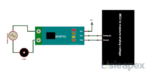
On the module's alternate side, three pins are present. Vcc connects to +5V to supply power to the module, while the ground links to the MCU (system) ground. Subsequently, the analog voltage produced by the ACS712 module is read using any analog pin available on the Microcontroller.
Tutorial about ACS712 Current Sensor with Arduino
ACS712 Current Sensor Pinout
Pinout
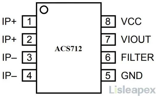
Pin Configuration
|
Pin Number |
Pin Name |
Description |
|
1 |
Vcc |
Input voltage is +5V for typical applications |
|
2 |
Output |
Outputs Analog voltage proportional to current |
|
3 |
Ground |
Connected to ground of the circuit |
|
T1 |
Wire In |
Terminal for the wire through which current is measured |
|
T2 |
Wire Out |
Terminal for the outgoing wire |
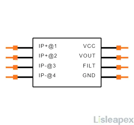
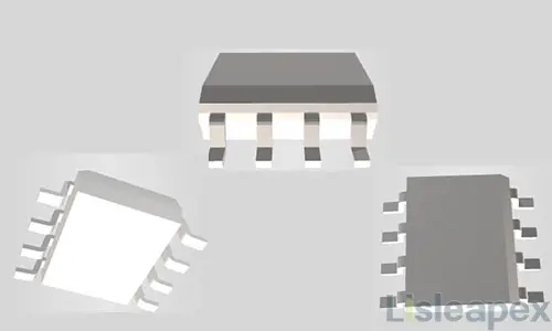
ACS712 Current Sensor CAD Model
Technical Specifications of ACS712 Current Sensor
Specifications
- Type: Analog Circuit
- Parameter: Current Sensor
- Factory Lead Time: 18 Weeks
- Mounting Type: Surface Mount
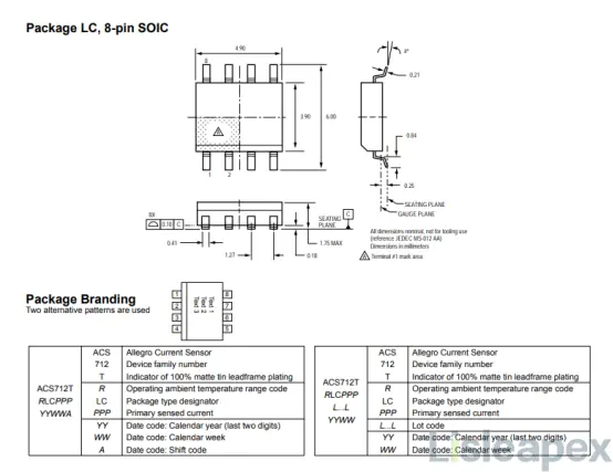
- Package / Case: 8-SOIC (0.154, 3.90mm Width), Surface Mount
- Number of Pins: 8
- Operating Temperature: -40°C to 85°C
- Packaging: Tape & Reel (TR)
- Publication Year: 2007
- JESD-609 Code: e3
- Pbfree Code: Yes
- Part Status: Not For New Designs
- Moisture Sensitivity Level (MSL): 2 (1 Year)
- Number of Terminations: 8
- Termination: SMD/SMT
- Terminal Finish: Matte Tin (Sn)
- Supply Voltage: 5V
- Terminal Position: Dual
- Terminal Form: Gull Wing
- Peak Reflow Temperature (Cel): 260
- Number of Functions: 1
- Operating Supply Voltage: 5V
- Number of Channels: 1
- Analog IC - Other Type: Analog Circuit
- Polarization: Bidirectional
- Output Current: 10mA
- Max Supply Current: 13mA
- Quiescent Current: 10mA
- Response Time: 5μs
- Bandwidth: 80 kHz
- Sensor Type: Hall Effect, Open Loop
- Linearity: ±1.5%
- For Measuring: AC/DC
- Current - Sensing: 20A
- Sensitivity (mV/A): 100 mV/A
- Height: 1.5mm
- Length: 4.9mm
- Width: 3.9mm
- REACH SVHC: No SVHC
- Radiation Hardening: No
- RoHS Status: ROHS3 Compliant
- Lead Free: Yes
Key Features
- Low-Noise Analog Signal Path: Minimized signal interference.
- Bandwidth Configuration via FILTER Pin: User-adjustable bandwidth.
- 5μs Output Rise Time: Swift response to input changes.
- 80kHz Bandwidth: Wide frequency range.
- 1.5% Total Output Error at 25°C: Low error rate.
- Compact SOIC8 Package: Space-efficient design.
- 1.2mΩ Internal Conductor Resistance: Minimal resistance.
- 2.1kVRMS Isolation Voltage: Safe operation.
- Single 5.0V Supply: Simple power requirement.
- 66-185mV/A Output Sensitivity: Versatile current measurements.
- Proportional Output Voltage: Reflects AC/DC currents.
- Factory-Trimmed Accuracy: Precision calibration.
- Stable Offset Voltage: Consistent output.
- Minimal Magnetic Hysteresis: Reliable performance.
- Ratiometric Output: Relative to supply voltage.
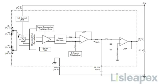
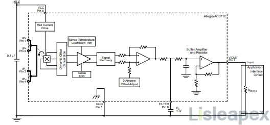
Functional Block Diagram of ACS712 Current Sensor
Alternative Part of ACS712 Current Sensor
- ACS759
- WCS1700
- KG190
- ACS715
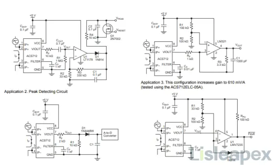
Applications and Usage of ACS712 Current Sensor
Application
- Regulating motor speed within motor control circuits.
- Detecting and managing electrical loads.
- Operating within switched-mode power supplies (SMPS).
- Providing protection against over-current situations.
Usage
When an external low pass filter is established for a typical Hall effect device, there might be a resistive divider between the filter resistor (RF) and the resistance of the customer interface circuit (RINTFC). This configuration results in significant attenuation, as indicated by the transfer function for ∆VATT.
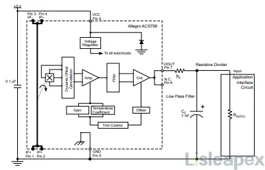
The ACS712 integrates an internal resistor, a connection for the FILTER pin on the PCB, and an internal buffer amplifier. This circuit configuration allows users to easily set up a basic RC filter by adding a capacitor, CF, connecting it from the FILTER pin to ground. The buffer amplifier within the ACS712, positioned after the internal resistor and FILTER pin connection, effectively eliminates the signal attenuation caused by the resistive divider effect described in the equation for ∆VATT. Consequently, the ACS712 device is exceptionally suitable for high-precision applications where avoiding signal attenuation, typically associated with an external RC low-pass filter, is critical.
Further Reading: How to Make a Digital Ammeter using PIC16F877A and ACS712-5A
ACS712 Current Sensor Programming
Before programming the microcontroller to read from the ACS712 Module, understand its default behavior: when no current flows, the output voltage is +2.5V (Vcc/2). Current flow in different directions alters this voltage from 2.5V, allowing measurement of both AC and DC currents.
Assuming a 10-bit ADC in a 5V operating microcontroller, ADC values range from 0 to 1024. Use the formula Vout (mV) = (ADC Value/1023) * 5000 to calculate output voltage.
Then, calculate current using: Current (A) = (Vout (mV) - 2500) / Scale factor. Scale factor varies based on the module's range, as specified in the module's details.
ACS712 Current Sensor Package
Accessing ACS712 Current Sensor Datasheet PDF
Download ACS712 datasheet here>>
Manufacturer
The ACS712 is manufactured by Allegro MicroSystems, LLC. They specialize in developing, manufacturing, and marketing high-performance semiconductors, with a focus on automotive, office automation, industrial, and consumer/communications solutions. Allegro MicroSystems is headquartered in Worcester, Massachusetts, USA, with various design, application, and sales support centers located worldwide.
FAQs
Q: What are the different types of ACS712 sensors available?
A: It is available in various models with different current rating ranges such as 5A, 20A, and 30A variants, allowing measurement of different levels of currents.
Q: What is the accuracy of the ACS712 sensor?
A: The accuracy of it varies based on the model but is typically specified around 1.5-2.0% of the measured value.
Q: How do you interface the ACS712 current sensor with a microcontroller or Arduino?
A: The output of the ACS712 sensor is an analog voltage. You can interface it with an analog input pin of a microcontroller (such as Arduino) to read the voltage proportional to the current.
Q: Can the ACS712 sensor measure both AC and DC currents?
A: Yes, it is capable of measuring both AC and DC currents.
Q: Does the ACS712 sensor require an external power supply?
A: It usually requires a power supply for its internal operation, but it doesn't need an external power supply for the current measurement itself.
Q: What precautions should be taken when using the ACS712 sensor?
A: Avoid exposing the sensor to extreme temperatures, handle it carefully to prevent damage to the Hall sensor, and ensure proper calibration for accurate readings.
Q: Can multiple ACS712 sensors be used together for measuring multiple currents?
A: Yes, they can be used simultaneously to measure multiple currents independently.
FAQ
-
What precautions should be taken when using the ACS712 sensor?
Avoid exposing the sensor to extreme temperatures, handle it carefully to prevent damage to the Hall sensor, and ensure proper calibration for accurate readings.
-
Does the ACS712 sensor require an external power supply?
It usually requires a power supply for its internal operation, but it doesn't need an external power supply for the current measurement itself.
-
Can the ACS712 sensor measure both AC and DC currents?
Yes, it is capable of measuring both AC and DC currents.
-
How do you interface the ACS712 current sensor with a microcontroller or Arduino?
The output of it is an analog voltage. You can interface it with an analog input pin of a microcontroller (such as Arduino) to read the voltage proportional to the current.
-
What is the accuracy of the ACS712 sensor?
The accuracy of the ACS712 sensor varies based on the model but is typically specified around 1.5-2.0% of the measured value.
-
What are the different types of ACS712 sensors available?
It is available in various models with different current rating ranges such as 5A, 20A, and 30A variants, allowing measurement of different levels of currents.
Stay updated with Lisleapex by signing up for the newsletter
