 Congratulations On Your Successful Submission
 Submission Failure
What is a 2-wire Sensor?
A two-wire sensor is a common industrial measurement sensor that uses two wires connected to the object being measured to measure physical quantities and transmit the results to a control system. The two-wire system means that the field transmitter is connected to the control room instrumentation with only two wires, which are both power and signal wires.
Features of 2-wire Sensor
- Two Wires: Only two wires are required for power and signal transmission.
- Loop Powered: These sensors typically operate in a series circuit, using the same wire for signaling and power.
- Performance Limitations: Sometimes the performance of the system, such as response time, can be affected by the additional current that is transmitted through the same wiring while the signal is being transmitted.
- Simple Wiring: These sensors are simpler to wire than other sensor configurations, requiring fewer wires and connections.
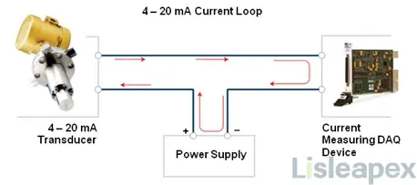
- Common in 4-20 mA Systems: In industrial environments, two-wire sensors are commonly used in 4-20 mA current loop systems with output signals ranging from 4 mA (minimum) to 20 mA (maximum), proportional to the parameter being measured.
2-wire Sensor Structure
The components of a two-wire sensor consist of a sensing element, a circuit and signal processing section, a two-wire V/I converter and a housing and protection layer. These components work in conjunction with each other to enable the sensor to reliably detect environmental parameters and generate the corresponding output signals.
#1 Sensing Components
This is the core component used to detect specific environmental parameters such as temperature, pressure, humidity, flow rate, etc. The design of the sensing element depends on the type of parameter to be measured and it is responsible for converting the environmental parameter into an electrical signal.
#2 Circuitry and signal processing section
This section is typically used to condition, process and amplify the electrical signals obtained from the sensing element. It can include amplifiers, filters, linearization circuits, etc. to ensure that the output signal meets specific standards and requirements.
#3 Two-wire V/I converter
A V/I converter is a circuit that can control the output current with a voltage signal. The difference between a two-wire V/I converter and a general V/I converter circuit is that the voltage signal does not directly control the output current, but rather controls the power consumption current of the entire circuit itself. At the same time, a stabilized voltage is extracted from the current loop to power the conditioning circuits and sensors. The attached figure shows the basic schematic of a two-wire V/I converter circuit:
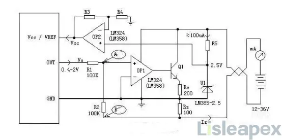
OP1, Q1, R1, R2 and Rs form the V/I converter in the figure. Analyze the negative feedback process: if point A is higher than 0V for some reason, the output of op-amp OP1 rises, the voltage at both ends of Re rises, and the current through Re becomes larger. This corresponds to the overall power consumption becoming larger, the current through the sampling resistor Rs also becomes larger, and the voltage at point B becomes lower (more negative).
#4 Housings and Protective Coatings
Sensors often require housings and protective coverings to protect the internal components from environmental influences (e.g. dust, moisture, etc.) and to ensure their stability and reliability.
Working Principle of 2-wire Sensor
The operating principle of a two-wire sensor is based on the following key steps: First, the sensor detects environmental parameters via internal sensing elements (e.g. temperature sensors, pressure sensors, etc.). Next, the sensor converts these detected parameters into a corresponding electrical signal. Next, this electrical signal is transmitted to the receiving device.
This process creates a loop in which the sensor utilizes the same pair of wires for power and signal transmission. In this loop, the sensors are connected in series to the power supply and the receiving device. This method of operation not only simplifies wiring, but also ensures that the sensors work reliably and consistently to convert environmental parameters into usable electrical signals that can be transmitted to the receiving device for further processing.
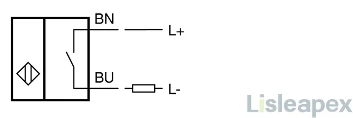
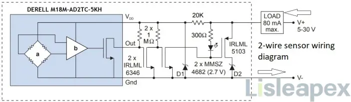
2-wire sensor wiring diagram
Here is the video about how the 2-wire sensor works,
Application of 2-wire Sensor
Two-wire sensors find applications across various industries due to their simplicity in installation and wiring. Some common applications include:
- Industrial Process Control: In manufacturing plants, 2-wire sensors are used for monitoring parameters like temperature, pressure, flow, and level. They help in maintaining optimal conditions and ensuring efficient operations.
- Environmental Monitoring: These sensors are employed in environmental monitoring systems to measure parameters such as humidity, air quality, and gas concentrations.
- Building Automation: 2-wire sensors are utilized in building automation systems for tasks like occupancy sensing, light level detection, and HVAC (heating, ventilation, and air conditioning) control.
- Utilities Management: They are used in utility management systems for monitoring water levels, gas meters, and electric power usage.
- Automotive Industry: In vehicles, 2-wire sensors are used for various measurements including engine temperature, oil pressure, and vehicle speed.
- Safety Systems: These sensors play a role in safety systems by detecting gas leaks, fire hazards, or abnormal environmental conditions.
- Machine Health Monitoring: They can be used in predictive maintenance systems to monitor machine vibrations, temperature, and other parameters to predict potential failures.
- Remote Monitoring: In remote or inaccessible locations, 2-wire sensors are preferred due to their simplicity in installation and reduced wiring requirements.
What are the Differences between 2-wire and 3-wire Sensor
The differences between 2-wire and 3-wire sensors primarily lie in their wiring configurations, power supply, and their ability to handle loads:
1. Wiring Configuration:
- 2-wire sensors are designed for series wiring with the load. They pass additional current through the same line they transmit data through. This configuration can potentially affect overall system performance.
- 3-wire sensors typically involve two terminals for supply and one for output. These sensors can be connected in serial or parallel configurations strategically to protect inputs or perform logic.
2. Power Supply:
- 2-wire sensors operate as loop-powered devices without requiring a separate supply voltage. They draw power from the source voltage supplied to the target device.
- 3-wire sensors are self-powered devices. They require a separate supply voltage to function, providing results regardless of the load on the output.
3. Performance Impact:
- 2-wire sensors may affect response time, as the response time is equal to the sum of the turn-on times of each device in the loop. Additionally, passing additional current through the same line might hinder system performance.
- 3-wire sensors can potentially handle larger impedance loads compared to 2-wire sensors at similar voltage levels. They offer more flexibility in configurations and generally maintain consistent performance regardless of load variations.
4. Connectivity and Flexibility:
- 2-wire sensors are easier to wire but might impact overall system performance due to the passing of additional current through the same line. They allow insertion anywhere in a loop in circuits with a positive or negative common.
- 3-wire sensors typically have fixed connections and require a separate supply voltage, but they can handle larger impedance loads and offer more flexibility in configuring serial or parallel connections for different purposes.
2-wire sensors operate as loop-powered devices with simpler wiring but potential performance impacts, while 3-wire sensors are self-powered, handle larger loads, and offer more flexibility in configurations. The choice between them depends on factors like load requirements, performance considerations, and wiring complexity within the intended system.
Differences between 2-, 3-,4-wire RDT Sensing
The differences between 2-, 3-, and 4-wire Resistance Temperature Detector (RTD) sensing methods lie in their wiring configurations and their impact on measurement accuracy and compensation for lead wire resistance:
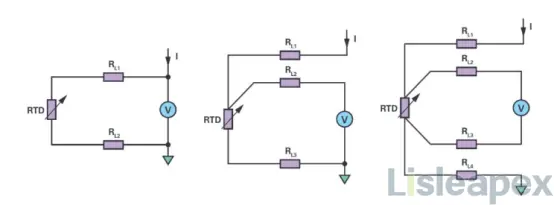
2-Wire RTD Sensing:
Configuration: In a 2-wire RTD sensing setup, the RTD is connected using two wires: one for current excitation and the other for signal measurement. However, this configuration does not account for the resistance of the lead wires, leading to measurement errors, especially in longer wire lengths or with high resistance materials.
3-Wire RTD Sensing:
Configuration: 3-wire RTD sensing uses three wires: two wires for current excitation and the third for signal measurement. This configuration compensates for the resistance of the lead wires, helping to eliminate the inaccuracies caused by the resistance of the wires themselves. It enhances measurement accuracy compared to 2-wire setups.
4-Wire RTD Sensing:
Configuration: 4-wire RTD sensing utilizes a four-wire setup: two wires for current excitation and two separate wires for signal measurement. This method completely eliminates the effects of lead wire resistance by using separate wires for excitation and signal measurement. It offers the highest accuracy among these methods.
In summary, while 2-wire RTD sensing is the simplest and most cost-effective, it can suffer from inaccuracies due to lead wire resistance. 3-wire configurations provide compensation for these resistances, enhancing accuracy. 4-wire RTD sensing completely eliminates lead wire resistance effects, offering the highest accuracy in temperature measurements.
FAQ
-
Are there specific considerations for troubleshooting 2-wire sensors?
Ensure proper power supply and verify connections and polarity. Signal interference or noise issues may require additional shielding or signal conditioning.
-
How do 2-wire sensors differ from 3-wire or 4-wire sensors?
3-wire and 4-wire sensors often separate the power supply and signal output lines, providing improved signal integrity and allowing longer distances without signal degradation compared to 2-wire sensors.
-
Can 2-wire sensors be used for long-distance applications?
While they are suitable for many applications, distance limitations might exist due to signal degradation over longer wire lengths.
-
What are the limitations of 2-wire sensors?
One limitation is the potential for signal interference due to the combined power and signal transmission on the same wire, which may affect the quality of the output signal.
-
Are 2-wire sensors easy to install and use?
Yes, they are generally easier to install due to the reduced wiring complexity. However, proper attention to polarity and connection points is necessary to ensure correct operation.
-
What are the advantages of 2-wire sensors?
Some advantages include simplified wiring, reduced installation complexity, and cost-effectiveness due to fewer wires needed for operation.
-
What is a 2-wire sensor?
A 2-wire sensor is a type of sensor that requires only two wires for its operation: one for power and the other for the signal output.
Stay updated with Lisleapex by signing up for the newsletter
